What Files Are Needed to Build a Useful Drone Map?
The core files for a useful drone map
A useful drone map depends on three essential file types: raw imagery, geospatial reference files, and a processed output format. Raw images capture the scene, geospatial files give each pixel a real-world coordinate, and output formats let you share or analyze the result. Without all three, the map is either incomplete or unusable for measurement.
Raw imagery: the foundation
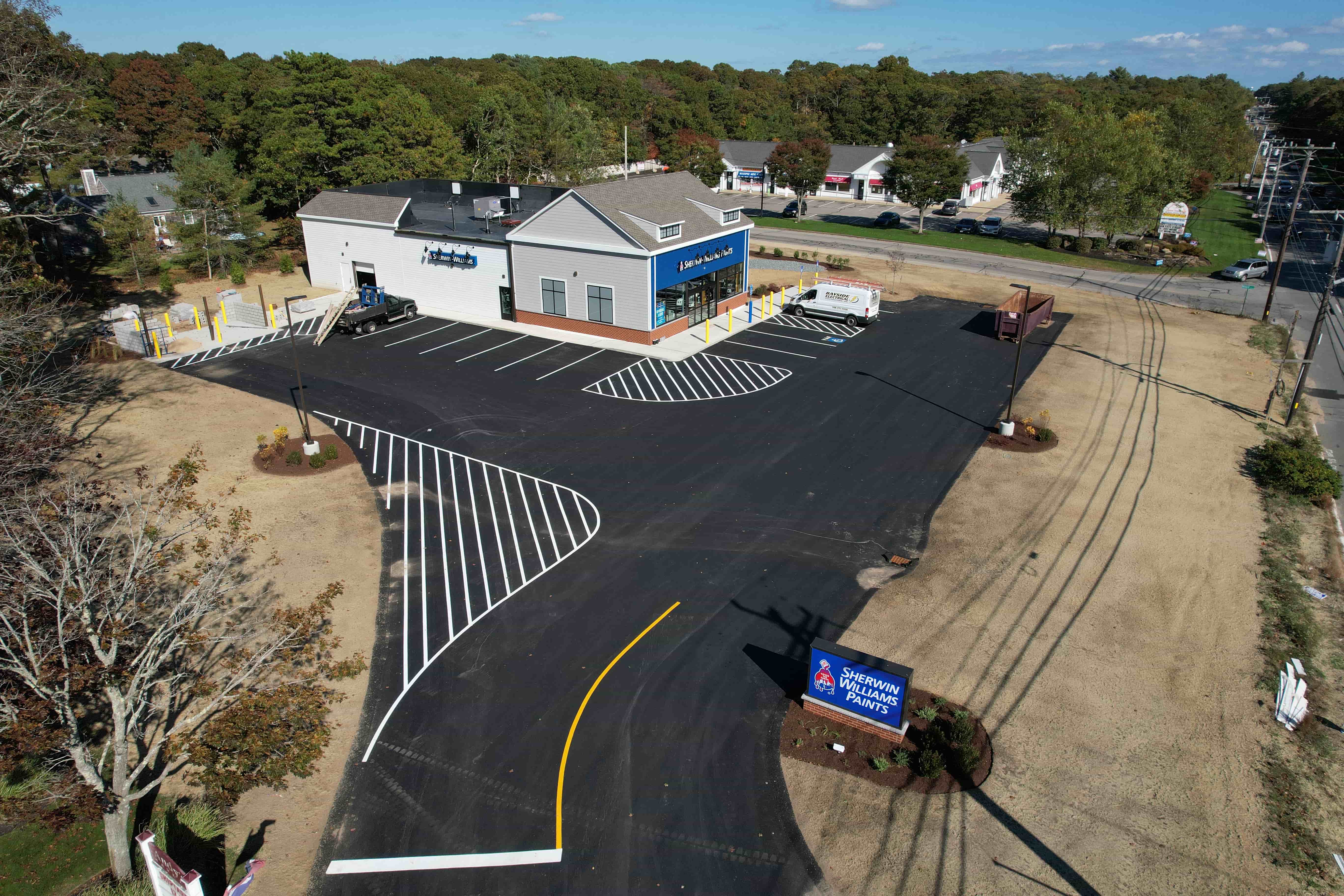
Every drone map starts with the original photos taken during flight. These are typically JPEG or TIFF files, often with embedded metadata called EXIF data that records camera settings, GPS coordinates, altitude, and lens information. The quality of these raw images directly affects everything downstream. A blurred image, incorrect white balance, or low resolution cannot be fully fixed later.
For mapping purposes, the key is to capture images with enough overlap. Standard practice is 70-80% forward overlap and 60-70% side overlap. This overlap allows photogrammetry software to find matching points between adjacent photos and reconstruct a 3D model. If overlap is too low, the software cannot stitch the images together reliably, and the resulting map will have gaps or distortions.
Ground sampling distance (GSD) is another critical factor. GSD tells you how much real-world area each pixel represents. A GSD of 2 cm per pixel means you can measure objects as small as a few centimeters, while a GSD of 10 cm per pixel is coarser. The GSD depends on flight altitude, camera sensor size, and lens focal length. Lower altitude gives finer detail but requires more images to cover the same area, increasing processing time and file count.
Storing raw imagery is straightforward: keep the original files in a folder with a clear naming convention that includes the date, location, and flight number. This helps when you need to reprocess the data later with updated software or different settings.
Geospatial reference files: giving the map a location
A drone map that shows only pixels is not yet useful for measuring distances, areas, or volumes. To make it useful, you must add geospatial reference data. This typically comes in one of two forms: ground control points (GCPs) or an existing georeferenced base map.
Ground control points are physical markers placed in the field before the flight. Each marker has known coordinates measured with a survey-grade GPS or total station. During processing, the photogrammetry software uses these known points to tie the drone images to real-world coordinates. The result is a map that is accurate to within a few centimeters. GCP files are usually stored as CSV or text files listing point ID, easting, northing, elevation, and sometimes an image coordinate.
If ground control points are not available, you can use a process called georeferencing against an existing orthomosaic or satellite image. This method is less accurate but works for many applications where absolute accuracy is not critical. The reference file might be a geoTIFF or a shapefile of known features such as roads, building corners, or field boundaries.
Coordinate system selection matters. Most drone mapping projects use a projected coordinate system such as UTM (Universal Transverse Mercator) or state plane. For elevation, the system can be ellipsoidal (based on the WGS84 ellipsoid) or orthometric (based on mean sea level). The choice affects how distances and volumes are calculated. It is important to use the same coordinate system for all files in a project to avoid misalignment errors.
Some drone mapping workflows also use a digital elevation model (DEM) from an existing source, such as a national lidar dataset, to help correct for terrain variation. This is especially useful when mapping hilly or mountainous areas where the ground is not flat.
Processed output formats: the final deliverable
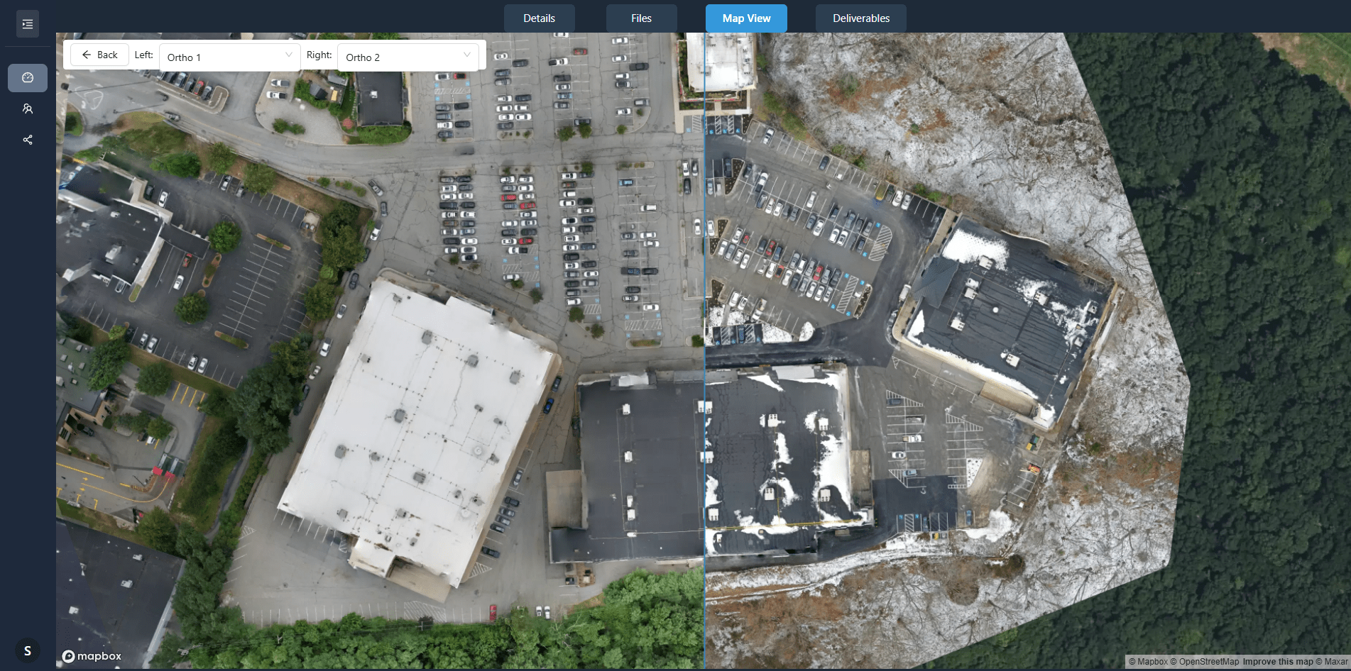
After raw imagery and reference data are combined, the software produces a set of output files. The most common is an orthomosaic: a single, seamless, geometrically corrected image that covers the entire area. Orthomosaics are usually saved as geoTIFF files, which embed the coordinate system and allow GIS software to read them directly. A geoTIFF can be quite large, often hundreds of megabytes or even gigabytes for a large site.
A point cloud is another common output. It represents the 3D surface as a collection of points, each with X, Y, and Z coordinates. Point clouds are typically stored in LAS or LAZ format (compressed LAS). They are useful for volume calculations, tree canopy analysis, and creating 3D models. The density of the point cloud depends on the overlap and the processing algorithm. Higher density means more detail but larger file size.
For many engineering and construction projects, a digital surface model (DSM) or digital terrain model (DTM) is required. These are raster files where each pixel holds an elevation value. A DSM includes all features on the surface, such as buildings and trees. A DTM strips away those features to show the bare earth. Both are usually saved as geoTIFFs or ASCII grids. The difference between DSM and DTM is important: using a DSM for volume calculations over a forested area will overestimate the volume because the tree canopy is counted as ground.
Some workflows also generate a 3D mesh in OBJ or PLY format, which can be used in CAD or visualization software. These are less common in surveying and more common in visual inspection or heritage documentation.
How the files work together
Imagine you are mapping a construction site. You fly the drone and capture 500 images. You also place three ground control points around the site. The processing software imports the images, reads the GPS metadata, and uses the ground control points to align everything. It then builds a point cloud, from which it creates an orthomosaic and a DSM. The final deliverables are a geoTIFF orthomosaic, a LAS point cloud, and a geoTIFF DSM. All three files are georeferenced in the same coordinate system, so they overlay perfectly in any GIS application.
If you only had the raw images, you could view them as separate photos, but you could not measure anything accurately. If you only had the orthomosaic, you could see the site but not the 3D shape. If you only had the point cloud, you would have 3D data but no color or texture. Together, they give you a complete picture.
Common pitfalls to avoid
One common mistake is using different coordinate systems across files. For example, if the raw images record GPS in WGS84 latitude/longitude but the ground control points are in UTM, the software must reproject one of them, which can introduce errors. Always check that all files share the same coordinate system before processing.
Another pitfall is insufficient overlap. Even with perfect images, low overlap will cause software to fail or produce a map with visible seams. It is better to fly with extra overlap and discard unnecessary images later than to fly with minimal overlap and hope it works.
File naming can cause confusion. If you rename raw images after processing, you lose the link between the output and the source. Keep a consistent naming convention and maintain a log of which images correspond to which ground control points.
Finally, be aware of file size limits. Some free software cannot handle point clouds larger than a few tens of millions of points. If your site is large, you may need to split it into smaller tiles or use software that supports streaming or tiled processing. National Drone Services offers a data platform that handles these large datasets efficiently, organizing them in client portals for easy viewing and delivery.
Choosing the right output for your purpose
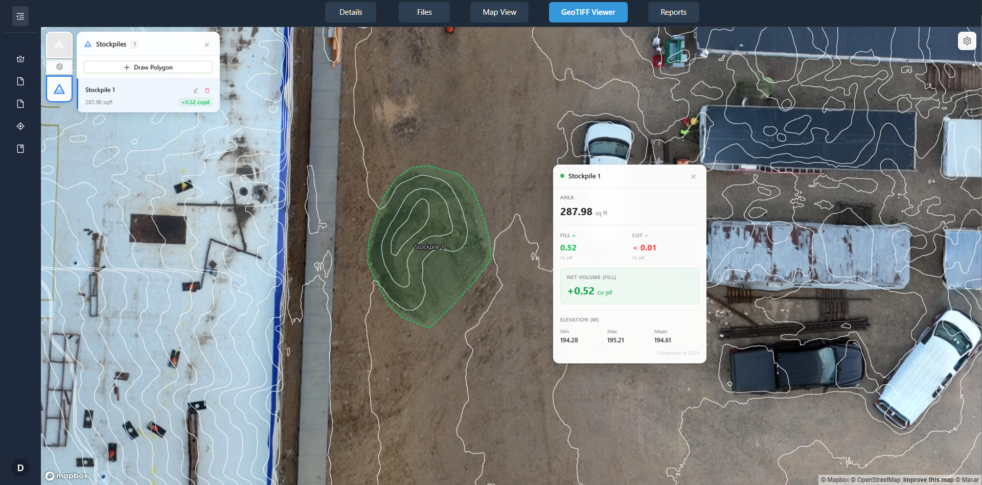
Not every project needs all file types. For a visual inspection of a roof, an orthomosaic might be enough. For a volume calculation of a gravel stockpile, you need a point cloud or a DSM. For an engineering design, you need a DTM with ground control points for high accuracy. Think about what you will actually do with the map before deciding which files to generate.
If you are delivering the map to a client, ask what software they use. Some GIS applications can read geoTIFF directly, while others need a shapefile or a KMZ. Many clients prefer a PDF with measurements over a raw geoTIFF. Tailoring the output format to the end user saves time and confusion.
For long-term archiving, keep the raw images and the ground control points. These are the original data and can be reprocessed with better software in the future. Processed outputs like orthomosaics are derived and may become obsolete if coordinate systems change or if higher-accuracy reference data becomes available. National Drone Services helps manage this workflow by providing a platform where all these file types can be uploaded, compared, and delivered in a structured way.
Summary of essential files
- Raw imagery (JPEG or TIFF with EXIF metadata)
- Ground control points or georeference files (CSV, shapefile, or existing orthomosaic)
- Processed output (orthomosaic geoTIFF, point cloud LAS/LAZ, DSM/DTM geoTIFF)
These three categories form the backbone of any useful drone map. The exact combination depends on your accuracy requirements, the size of the area, and what you plan to measure. By understanding what each file contributes, you can plan a flight and processing workflow that delivers exactly what you need.